View Hvac Fan Switch Wiring Diagram Images. 4 wires is a common question by new techs. Programmable thermostat wiring diagrams installing a programmable thermostat is not unlike installing any other thermostat for your hvac system.
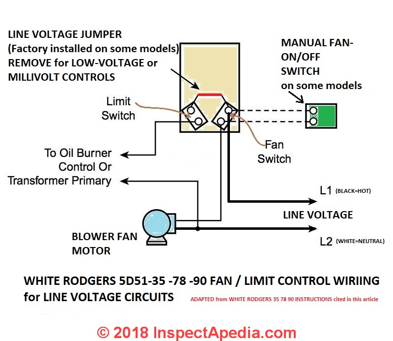
How to Install & Wire the Fan & Limit Controls on Furnaces ... from inspectapedia.com Symbols you should know the standard or fundamental elements used in a wiring diagram include power supply, ground, wire and connection, switches, output devices, logic gate, resistors, light, etc. At first glance, hvac wiring diagrams look intimidating, just as intimidating as a roadmap did the first time you glanced at one of those. Each fan has been thoroughly checked to ensure high efficient and quiet operation.
As can be seen in the diagram the wiring is pretty simple.
Type of wiring diagram wiring diagram vs schematic diagram how to read a wiring diagram: Here a simple spst switch is used to supply power or not to the fan motor and a regulator is used to controlling the fan speed. Hvac hvacr wiring diagrams schematics low voltage 24v ac high voltage 120 volt 240 volt thermostat sequence of operation voltage path colors terminals functions air conditioner heat pump thermopile safety switch. The above points can be fulfilled by understanding the electrical wiring diagram of individual hvac equipment and of the whole system also.

0 Response to "Hvac Fan Switch Wiring Diagram"
Post a Comment